Ex-Link Cable for C/D/E Series and BD players
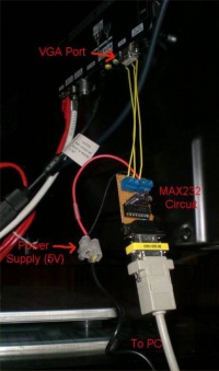
On most C-Series devices, the Ex-Link port is located on the VGA connector of the TV. While on the ES-series, there is a separate 3.5mm jack labelled as "Service".
This page explains how to access the serial on these devices.
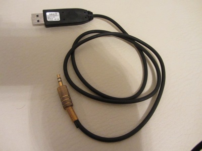
If you don't feel capable of soldering such a cable, you can find and buy a cheap (under $5) USB to TTL adapter at eBay. However, experience have shown that some of these cheaper cables can be unreliable and more difficult to be made to work because of lacking documentation, drivers and source code. You get what you pay for. So if you wanna have a fully supported and very well made USB-to-serial (RS232 @ 3.3V) cable, I'd recommend the much more expensive FTDI cables.
Contents
- 1 Enable Debug mode in service menu
- 2 Wireless ExLink module for C/D/E series
- 3 Wired ExLink cable
- 4 ES series Ex-Link cable and Service Port connection
- 5 Using Arduino to access Serial Console with telnet
- 6 Start the terminal
- 7 Read output
- 8 Enabling serial input and recover your TV from bricked hack
Prerequisite: Set the RS232 Jack to "Debug" in the Service_Menu.
- In service menu, enable Debug mode for the RS232 port:
- With TV switched off, press the following sequence on the remote:
- UE,LE models:[INFO] [MENU] [MUTE] [POWER]
- UN,UA models:[MUTE] 1 8 2 [POWER]
- UE,LE models:[INFO] [MENU] [MUTE] [POWER]
- Enter the Control menu and set the value of the RS232 mode to Debug.
- Once you're back to the main Service menu, you will have to power off the TV for normal operation.
- Notice that your TV will reset RS232 mode back to UART when you install another firmware (no matter if it's older or newer).
- With TV switched off, press the following sequence on the remote:
Wireless ExLink module for C/D/E series
- Check this topic on the forum
- To be updated...
Wired ExLink cable
As the TV uses 3.3V TTL levels, the serial input/output has to be converted to/from TTL levels to RS232 levels (~10-15V). Thus a level shifter is needed. But most computers today, doesn't have an RS232 port, so you also need a USB-to-RS232 serial adapter (cable). Thus its a definite advantage to buy a pre-fabricated USB-to-serial converter using 3.3 Volt TTL levels on the serial side. Common one to look for are based on the PL2303 and FTDI chips.
WARNING! RS232 levels are up to 15V, which can cause seriously damage at your TV!
You need to use either Nokia CA-42 or MAX232 based cable from steps below, you don`t need to solder both ;)
Nokia CA-42/DKU-5 USB
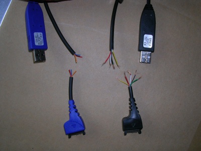
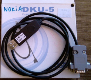
This is a common, but old, Nokia (phone) data cable, that cost less than 3 EUR. All, you have to do to convert it to a ExLink cable is the following modification. Unfortunately this cable is not that easy to find anymore so buying one of the other USB-to-serial cables are recommended.
What you will need:
- Some soldering skills.
- Some means of determining continuity (e.g. a multimeter + hand-held probe leads).
- Some means of stripping insulated wires.
- A willingness to invalidate your warranty.
- A CA-42, or DKU-5 (some later Nokia phone cables e.g. the DKU-2, CA-53, CA-70 - which look similar are actually pure USB cables with no transceiver - DON'T use these, they won't work.
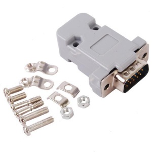
- 15 Pin Male VGA Case Replacement Adapter Set Assembly
- Suitable safety gear.
- Pliers, glue/tape, and volt meter (optional).
- PL2303 driver
Cut and Strip Insulation from the Cable
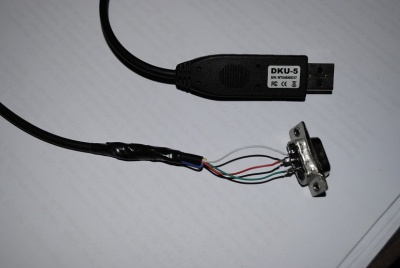
Cut the data cable about 60mm from the Nokia connector end, strip away approx 20mm of the outer sheath, and remove approx 3mm of insulation from each inner core.
The cables I bought were of two different designs, this may well vary from manufacturer to manufacturer.
1.CA-42 cable, and had 3 wires - ground, data transmit, and data receive.
2.DKU-5 cable had 5 wires - well as txd, rxd, gnd and additional wires can be safely left disconnected.
Identify Each Wire
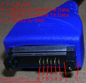
Establish which core is connected to which pin on the Nokia connector end (Nokia "pop port") using your continuity tester. The part of the "pin-out" which we care about are:
- pin 1 On both of the cables I used, pin 1 is actually missing.
- pin 2 On both of the cables I used, pin 2 is also missing.
- pin 3 (normal length) connected to one of the wires on DKU5, but not needed (isolate this wire)
- pin 4 (sticks out a bit further)+3.3v this is used to power the transceiver on the DKU-5 cable I have (red), but not the CA-42
- pin 5 (not connected)
- pin 6 (normal length) serial Rxd
- pin 7 (normal length) serial Txd
- pin 8 (sticks out a bit further) Signal Ground (GND)
- pin 9 to 14 not connected, and missing on both my connectors
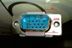
Now get the wires that goes to pin 6,7,8. As you already identified which are Rx, Tx, GND, have to connect/solder the CA-42/DKU-5 wires with the 15 Pin Male VGA Case Replacement Adapter Set Assembly
and build this:
Install PL2303 drivers to PC
NB! You have to install PL2303 drivers to PC to get your cable working.
Download from here.
Build MAX232 based cable
- Pin 4 at the VGA connector is RX (from the TV's point of view)
- Pin 11 at the VGA connector is TX (from the TV's point of view)
- Pin 5,6,7,8 and the case at the VGA connector are GND
MAX232 adaptor circuit V1
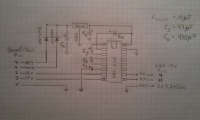
Here is a simple circuit using a MAX232 chip to convert the signal from TTL to RS232 level.
The Pinout of the connectors is shown at the circuit:
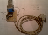
And a picture of the completely assembled board:
MAX232 adaptor circuit V2
See here [1]
Warning
As mentioned before, never connect your TV directly to the serial port of your PC (if you have one), since
the TV is using 3.3V TTL logic levels and the PC has normal RS232-level, you could seriously damage your
TV by a direct connection!
Connection chain over USB
Recent PCs do not have a RS232 port anymore, but there are USB adaptors available. Most of them use a PL2303 chip for converting the RS232 signal to USB.
The following figure shows the connection chain:

This could look like:
ES series Ex-Link cable and Service Port connection
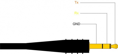
The Ex-Link cable for ES series is similar to all other serial cables except that it is terminated by 3.5mm stereo plug. However, this has caused some confusion, as most instructions showing how to build the 3.3V Ex-Link serial cable is based on a misinterpretation of the serial connection, because the female part of the 3.5mm stereo jack on the TV side, is never shown. In addition it can be confusing to know what hole to connect to as there are two very similar ones on the back of the ES models. One is for audio and the other is for "service". You need to connect to the service (debug) port.
The picture shown below is in fact just a small part of the one shown on the FTDI TTL-232R-3V3-AJ datasheet for the plug side of the USB-to-serial cable. Thus the Rx and Tx shown, are from the PC side of the serial adapter. Therefore you need to swap the Rx & Tx before connecting them to the Service port jack.
Also, please note that Prolific PL2303 based serial converters are notorious for having and creating problems, including finding appropriate drivers. I really recommend FTDI for any serious serial related stuff. They make great cables and have all their drivers supported in Windows/Linux and Android etc, including the source code in case you need compile your own. They also have easy access to great and easy to understand documentation. Yes, they are much more expensive, but you get what you pay for.
Here is an example for a Nokia CA-42 based Ex_Link Cable:
CA-42 Nokia <=> 3,5" jack TV
-----------------------------------
    Tx    6 <-> 2   Rx
    Rx    7 <-> 1   Tx
    GND   8 <-> 3   GND
Using Arduino to access Serial Console with telnet
See Ethernet to IR and Serial Console Interface
Start the terminal
Linux PC
On a Linux PC, install 'cu' (call up) tool from the uucp package and run
cu -l /dev/ttyUSB0 -s 115200
Windows PC
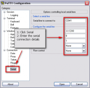
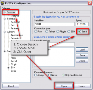
On Windows, we recommend the free terminal application Putty or RealTerm (download). But HyperTerminal is also very nice, but not free.
After you have started PuTTY, follow the steps in the screen shots below.

Read output
Output should be human readable, like in the following listing. If you get nothing, then your cabling/settings are incorrect. If you get garbage, then you have problems with the MAX232 circuit.
================================================================================
 SAMSUNG: v2.6.24_SELP_4.3.x_GA(P20)
         (Detailed Information: /sys/selp/vd/lspinfo/summary)
================================================================================
        2.0 : 0 : 256
init started: SELP-BusyBox v1.6.0-VD Linux SELP.4.2.1.x (2010-01-21 19:31:50 KST                                                                                                                               ) multi-call binary
starting pid 29, tty '/dev/ttyS1': '/etc/rcS'
/etc/rcS start!!!!
=====================================================
  ROOTFS VERSION : 65-1G-65
=====================================================
        it's not dev!
starting pid 43, tty '/dev/ttyS1': '/bin/sh'
-sh: id: not found
1st partition!!
/dtv/PART_FLAG_0  is detected...
1st Partition is selected....
Enabling serial input and recover your TV from bricked hack
The access codes in this section are device and firmware dependent. Please check forums, in case the codes below doesn't work.
- Connect your communications software and open the serial port
I usually use Mac. Even I could open the port and I could see the info from the TV I couldn't interact with keyboard.
So I decided to use HyperTerminal. The old Windows built-in communications software.
Windows 7 does not include this software, but you can download it from the web. Just Google it.
- Turn on your TV set, if everything is connected like described at the steps before the serial log should be shown at the serial terminal.
- The TV will keep on sending info, but when the debug log slow down a bit, send next command.
- Enter 10041004 (when typing the digits No Input is shown at the serial terminal) and confirm with Enter.
- In my case the SERIAL INPUT MANAGE was activated just pressed 10041004. No ENTER was needed.
after that you should see:
[SERIAL INPUT MANAGE] serial input ENABLE!!!!!
- Now enter 81588
- You will see this:
Aleady made Scenario File...so delete file
@@@@@@@@@@@ Key Record Start @@@@@@@@@@@
- Now enter 20089999
- You will see this:
====================================
      [ TOP Debug Menu]
------------------------------------
  1  : SubSystem Print On/Off
  2  : Platform Print Setting
  3  : TD Print Setting
  4  : Performance Print Setting
  5  : Sdal Print Setting
  6  : Sdal Trace Setting
  10 : Factory Debug
  11 : TD Debug
  12 : SubSystem DBG
  13 : SubSystem Info Print
  20 : Performance File Write
  21 : Louvre Print Setting
------------------------------------
  70 : Jade Debug
  80 : PVR Debug
====================================
  99 : Exit
====================================
DBG> :
- Now enter 2
- You will see this:
Input Start Level << :
- Now enter 0
- You will see this:
Input End Level << :
- Now enter 0
- You will see this:
====================================
     [Platform Debug List]
------------------------------------
  1. Basic Platform
  2. Advanced Platform
  3. Java
------------------------------------
  99 : Exit
====================================
cmd>
- Now enter 2
- You will see this:
====================================
     [Platform Debug List]
------------------------------------
  1 : FrontRunner Debug
  2 : DeviceManager Debug
  3 : InfoLink Debug
  4 : NetworkManager Debug
  5 : PVR Debug
  6 : MediaPlay Debug
  7 : CEC Debug
  8 : PSA Debug
  9 : SWU Debug
  10 : DMR Debug
  11 : PMR Debug
  12 : HNC Debug
  13 : MoIP Debug
------------------------------------
  99 : Exit
====================================
cmd>
- Now enter 2
- You will see this:
====================================
     [DeviceManager Debug Module]
------------------------------------
  1 : [OFF] DevMgr        2 : [OFF] DevMgr_SS
====================================
 Debug Level = Fatal
====================================
 80 : All OFF
 81 : All ON
 85 : Set Debug Level
====================================
 90 : DeviceManager MW Debug
 91 : DeviceManager SS Debug
 92 : ROSE Print Setting
 93 : ROSE Debug (For UNIPLAYER)
 99 : Exit
====================================
cmd>
- Now enter 90
- You will see this:
       ====================================
             [ Device Manager - TOP Debug Menu]
       ------------------------------------
          01  : Start DeviceManager
          02  : Stop DeviceManager
          03  : Suspend Mode Test
          04  : Start Stress Test
          05  : Stop Stress Test
       ------------------------------------
          11  : USB Test
          12  : DLNA, FLASH, ODD, HDD, MoIP Test
       ====================================
          21  : Print ALL Device Info
          22  : Print Device Info with KEY
          23  : Print ALL Partition Info
       ====================================
          FF : Exit
       ====================================
       DBG> : 0x
- Now enter 12
- You will see this:
       ====================================
             [ MISC Debug Menu]
       ------------------------------------
          01  : PRINT DLNA Device Info
          02  : PRINT FLASH Device Info
          03  : PRINT ODD Device Info
          04  : PRINT HDD Device Info
          05  : PRINT MoIP Device Info
       ====================================
          11  : FLASH, HDD Format Test
       ====================================
          88  : Shell
       ====================================
          FF : Exit
       ====================================
       DBG> : 0x
- Now enter 11
- You will see this:
Input Partition Key :
- Now enter, mtd_rwarea partition number. How to check partition number and some known partition numbers are here.
NB! You can damage your TV if wrong partition number is entered!
- If everything goes OK you will see the status of the filesystem and information about if partition has been formated:
Filesystem           1k-blocks      Used Available Use% Mounted on
/dev/tbml6                3456      3456         0 100% /
none                     10240         4     10236   0% /dtv
none                     10240         0     10240   0% /dsm
none                    235556         0    235556   0% /core
none                     10240         0     10240   0% /tmp
/dev/stl0/14             25478      2480     22998  10% /mtd_rwarea
/dev/stl0/19             49664     49664         0 100% /mtd_rocommon
/dev/stl0/15             91080     87336      3744  96% /mtd_exe
/dev/stl0/16             40832     40832         0 100% /mtd_appdata
/dev/stl0/13             10942       130     10812   1% /mtd_contents
/dev/stl0/20            102368     47600     54768  46% /mtd_swu
/dev/stl0/21            401712     76112    325600  19% /mtd_rwcommon
Filesystem           1k-blocks      Used Available Use% Mounted on
/dev/tbml6                3456      3456         0 100% /
none                     10240         4     10236   0% /dtv
none                     10240         0     10240   0% /dsm
none                    235556         0    235556   0% /core
none                     10240         0     10240   0% /tmp
/dev/stl0/19             49664     49664         0 100% /mtd_rocommon
/dev/stl0/15             91080     87336      3744  96% /mtd_exe
/dev/stl0/16             40832     40832         0 100% /mtd_appdata
/dev/stl0/13             10942       130     10812   1% /mtd_contents
/dev/stl0/20            102368     47600     54768  46% /mtd_swu
/dev/stl0/21            401712     76112    325600  19% /mtd_rwcommon
rootfs on / type rootfs (rw)
/dev/root on / type squashfs (ro)
none on /proc type proc (rw)
none on /sys type sysfs (rw)
none on /dev/sam type tmpfs (rw)
none on /dtv type tmpfs (rw)
none on /dsm type tmpfs (rw)
none on /core type tmpfs (rw)
none on /tmp type tmpfs (rw)
/dev/stl0/19 on /mtd_rocommon type squashfs (ro)
/dev/stl0/15 on /mtd_exe type rfs (ro,codepage=cp949,vfat,fcache(blks)=128)
/dev/stl0/16 on /mtd_appdata type squashfs (ro)
/dev/stl0/13 on /mtd_contents type rfs (rw,codepage=utf8,vfat,fcache(blks)=128)
/dev/stl0/20 on /mtd_swu type rfs (rw,codepage=cp949,vfat,fcache(blks)=128)
/dev/stl0/21 on /mtd_rwcommon type rfs (rw,codepage=utf8,vfat,fcache(blks)=128)
none on /proc/bus/usb type usbfs (rw)
This program is operated over FSR based
The flash memory blocks have been erased successfully.
+---------------------------------------------------------------------+
|  stl.format : STL-level Partitioning Tool for Flash Block Devices   |
+---------------------------------------------------------------------+
This partition does not have GWL attribute
[Block size  : 256 KB]
[Total unit  :    112]
[Block Device Information for /dev/bml0/14]
--------------------------------------------
 Total number of sectors = 51200 (25 MB/28 MB)
--------------------------------------------
STL format complete.
Success to format
Filesystem           1k-blocks      Used Available Use% Mounted on
/dev/tbml6                3456      3456         0 100% /
none                     10240         4     10236   0% /dtv
none                     10240         0     10240   0% /dsm
none                    235556         0    235556   0% /core
none                     10240         0     10240   0% /tmp
/dev/stl0/19             49664     49664         0 100% /mtd_rocommon
/dev/stl0/15             91080     87336      3744  96% /mtd_exe
/dev/stl0/16             40832     40832         0 100% /mtd_appdata
/dev/stl0/13             10942       130     10812   1% /mtd_contents
/dev/stl0/20            102368     47600     54768  46% /mtd_swu
/dev/stl0/21            401712     76112    325600  19% /mtd_rwcommon
/dev/stl0/14             25478       130     25348   1% /mtd_rwarea
rootfs on / type rootfs (rw)
/dev/root on / type squashfs (ro)
none on /proc type proc (rw)
none on /sys type sysfs (rw)
none on /dev/sam type tmpfs (rw)
none on /dtv type tmpfs (rw)
none on /dsm type tmpfs (rw)
none on /core type tmpfs (rw)
none on /tmp type tmpfs (rw)
/dev/stl0/19 on /mtd_rocommon type squashfs (ro)
/dev/stl0/15 on /mtd_exe type rfs (ro,codepage=cp949,vfat,fcache(blks)=128)
/dev/stl0/16 on /mtd_appdata type squashfs (ro)
/dev/stl0/13 on /mtd_contents type rfs (rw,codepage=utf8,vfat,fcache(blks)=128)
/dev/stl0/20 on /mtd_swu type rfs (rw,codepage=cp949,vfat,fcache(blks)=128)
/dev/stl0/21 on /mtd_rwcommon type rfs (rw,codepage=utf8,vfat,fcache(blks)=128)
none on /proc/bus/usb type usbfs (rw)
/dev/stl0/14 on /mtd_rwarea type rfs (rw,codepage=utf8,vfat,fcache(blks)=128)
- Now your system is clean. On next reboot your TV will regenerate that partition, and your devices will be mounted again as before.
- Now you've learn this lesson, you can hack your TV again :)
