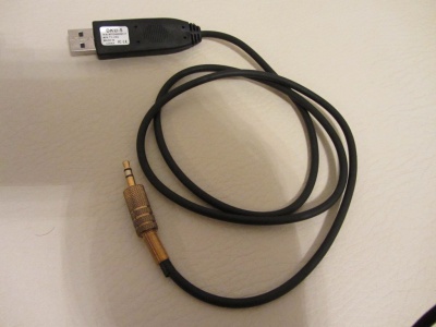
Ex-Link Cable for C/D/E Series and BD players
On most C-Series devices, the Ex-Link port is located on the VGA connector of the TV. While on the ES-series, there is a separate 3.5mm jack labelled as "Service".
This page explains how to access the serial on these devices.
If you don't feel capable of soldering such a cable, you can find and buy a cheap (under $5) USB to TTL adapter at eBay. However, experience have shown that some of these cheaper cables can be unreliable and more difficult to be made to work because of lacking documentation, drivers and source code. You get what you pay for. So if you wanna have a fully supported and very well made USB-to-serial (RS232 @ 3.3V) cable, I'd recommend the much more expensive FTDI cables.
Contents
Prerequisite: Set the RS232 Jack to "Debug" in the Service_Menu.
- In service menu, enable Debug mode for the RS232 port:
- With TV switched off, press the following sequence on the remote:
- UE,LE models:[INFO] [MENU] [MUTE] [POWER]
- UN,UA models:[MUTE] 1 8 2 [POWER]
- UE,LE models:[INFO] [MENU] [MUTE] [POWER]
- Enter the Control menu and set the value of the RS232 mode to Debug.
- Once you're back to the main Service menu, you will have to power off the TV for normal operation.
- Notice that your TV will reset RS232 mode back to UART when you install another firmware (no matter if it's older or newer).
- With TV switched off, press the following sequence on the remote:
Wireless ExLink module for B/C/D/E series
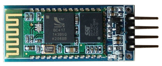
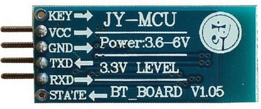
You need a bluetooth module for this job. They are from $5 to $10. But you are better to have with "backplane" versions for +$1,5 instead of bare module if you don't want to solder it. And blackplane versions have voltage regulator, since this modules are designed to work with 3.3v. Indeed, they are also work with 5v without issue on my tests. But it's out of the specification...
Anyway, here is the some dongles that you can buy.
Bluetooth HC07 module with Backplane 4 Pins
Bluetooth HC06 module with Backplane 6 Pins
Bluetooth HC?? module with Backplane 4 Pins
- Connect the "Key" and "VCC" with 10K/100K/1M resistor or something to VCC.
- Connect your bluetooth module from computer with RS232 TTL. (You can't configure module from bluetooth connection.)
- Configure dongle to work as 115200 baud with AT commands.
- For Bluetooth Modules with HC05 Firmware : AT+UART=115200,0,0
- For Bluetooth Modules with HC06 Firmware : AT+BAUD8
- Remove the "Key" and "Vcc" and reconnect dongle from Bluetooth.
- Test your dongle by connecting TX and RX pins together. Connect from bluetooth and you need read what you send to device.
- Than connect RX,TX, and GROUND connections to DSUB as ordinary. You need to receive power from USB port.
Cut and strip a USB wire and use only "RED Wire" to connect to Bluetooth dongle VCC. You can also connect the "BLACK wire" to GND pin instead of DSUB's GND. That's all.
- You can check this topic on the forum
Wired ExLink cable
As the TV uses 3.3V TTL levels, the serial input/output has to be converted to/from TTL levels to RS232 levels (~10-15V). Thus a level shifter is needed. But most computers today, doesn't have an RS232 port, so you also need a USB-to-RS232 serial adapter (cable). Thus its a definite advantage to buy a pre-fabricated USB-to-serial converter using 3.3 Volt TTL levels on the serial side. Common one to look for are based on the PL2303 and FTDI chips.
WARNING! RS232 levels are up to 15V, which can cause seriously damage at your TV!
You need to use either Nokia CA-42 or MAX232 based cable from steps below, you don`t need to solder both ;)
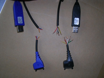
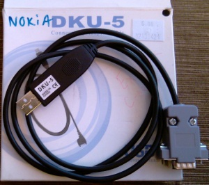
Nokia CA-42/DKU-5 USB
This is a common, but old, Nokia (phone) data cable, that cost less than 3 EUR. All, you have to do to convert it to a ExLink cable is the following modification. Unfortunately this cable is not that easy to find anymore so buying one of the other USB-to-serial cables are recommended.
What you will need:
- Some soldering skills.
- Some means of determining continuity (e.g. a multimeter + hand-held probe leads).
- Some means of stripping insulated wires.
- A willingness to invalidate your warranty.
- A CA-42, or DKU-5 (some later Nokia phone cables e.g. the DKU-2, CA-53, CA-70 - which look similar are actually pure USB cables with no transceiver - DON'T use these, they won't work.
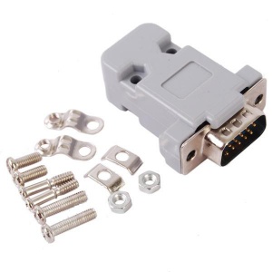
- 15 Pin Male VGA Case Replacement Adapter Set Assembly
- Suitable safety gear.
- Pliers, glue/tape, and volt meter (optional).
- PL2303 driver
Cut and Strip Insulation from the Cable
Cut the data cable about 60mm from the Nokia connector end, strip away approx 20mm of the outer sheath, and remove approx 3mm of insulation from each inner core.
The cables I bought were of two different designs, this may well vary from manufacturer to manufacturer.
1.CA-42 cable, and had 3 wires - ground, data transmit, and data receive.
2.DKU-5 cable had 5 wires - well as txd, rxd, gnd and additional wires can be safely left disconnected.
Identify Each Wire
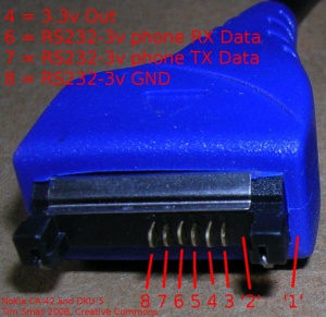
Establish which core is connected to which pin on the Nokia connector end (Nokia "pop port") using your continuity tester. The part of the "pin-out" which we care about are:
- pin 1 On both of the cables I used, pin 1 is actually missing.
- pin 2 On both of the cables I used, pin 2 is also missing.
- pin 3 (normal length) connected to one of the wires on DKU5, but not needed (isolate this wire)
- pin 4 (sticks out a bit further)+3.3v this is used to power the transceiver on the DKU-5 cable I have (red), but not the CA-42
- pin 5 (not connected)
- pin 6 (normal length) serial Rxd
- pin 7 (normal length) serial Txd
- pin 8 (sticks out a bit further) Signal Ground (GND)
- pin 9 to 14 not connected, and missing on both my connectors
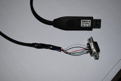
Now get the wires that goes to pin 6,7,8. As you already identified which are Rx, Tx, GND, have to connect/solder the CA-42/DKU-5 wires with the 15 Pin Male VGA Case Replacement Adapter Set Assembly
and build this:
Install PL2303 drivers to PC
NB! You have to install PL2303 drivers to PC to get your cable working.
Download from here.
Build MAX232 based cable
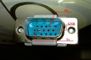
- Pin 4 at the VGA connector is RX (from the TV's point of view)
- Pin 11 at the VGA connector is TX (from the TV's point of view)
- Pin 5,6,7,8 and the case at the VGA connector are GND
MAX232 adaptor circuit V1
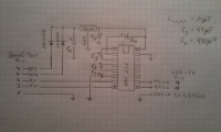
Here is a simple circuit using a MAX232 chip to convert the signal from TTL to RS232 level.
The Pinout of the connectors is shown at the circuit:
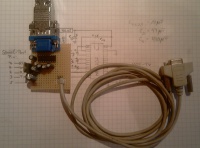
And a picture of the completely assembled board:
MAX232 adaptor circuit V2
See here [1]
Warning
As mentioned before, never connect your TV directly to the serial port of your PC (if you have one), since
the TV is using 3.3V TTL logic levels and the PC has normal RS232-level, you could seriously damage your
TV by a direct connection!
Connection chain over USB
Recent PCs do not have a RS232 port anymore, but there are USB adaptors available. Most of them use a PL2303 chip for converting the RS232 signal to USB.
The following figure shows the connection chain:

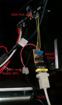
This could look like:
ES series Ex-Link cable and Service Port connection
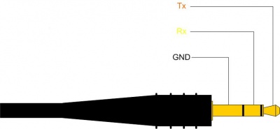
The Ex-Link cable for ES series is similar to all other serial cables except that it is terminated by 3.5mm stereo plug. However, this has caused some confusion, as most instructions showing how to build the 3.3V Ex-Link serial cable is based on a misinterpretation of the serial connection, because the female part of the 3.5mm stereo jack on the TV side, is never shown. In addition it can be confusing to know what hole to connect to as there are two very similar ones on the back of the ES models. One is for audio and the other is for "service". You need to connect to the service (debug) port.
The picture shown below is in fact just a small part of the one shown on the FTDI TTL-232R-3V3-AJ datasheet for the plug side of the USB-to-serial cable. Thus the Rx and Tx shown, are from the PC side of the serial adapter. Therefore you need to swap the Rx & Tx before connecting them to the Service port jack.
Also, please note that Prolific PL2303 based serial converters are notorious for having and creating problems, including finding appropriate drivers. I really recommend FTDI for any serious serial related stuff. They make great cables and have all their drivers supported in Windows/Linux and Android etc, including the source code in case you need compile your own. They also have easy access to great and easy to understand documentation. Yes, they are much more expensive, but you get what you pay for.
Here is an example for a Nokia CA-42 based Ex_Link Cable:
CA-42 Nokia <=> 3,5" jack TV
-----------------------------------
    Tx    6 <-> 2   Rx
    Rx    7 <-> 1   Tx
    GND   8 <-> 3   GND
Using Arduino to access Serial Console with telnet
See Ethernet to IR and Serial Console Interface
Start the terminal
Linux PC
On a Linux PC, install 'cu' (call up) tool from the uucp package and run
cu -l /dev/ttyUSB0 -s 115200
Windows PC
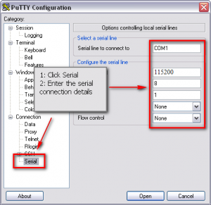
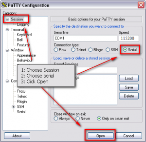
On Windows, we recommend the free terminal application Putty or RealTerm (download). But HyperTerminal is also very nice, but not free.
After you have started PuTTY, follow the steps in the screen shots below.

Read output
Output should be human readable, like in the following listing. If you get nothing, then your cabling/settings are incorrect. If you get garbage, then you have problems with the MAX232 circuit.
================================================================================
 SAMSUNG: v2.6.24_SELP_4.3.x_GA(P20)
         (Detailed Information: /sys/selp/vd/lspinfo/summary)
================================================================================
        2.0 : 0 : 256
init started: SELP-BusyBox v1.6.0-VD Linux SELP.4.2.1.x (2010-01-21 19:31:50 KST                                                                                                                               ) multi-call binary
starting pid 29, tty '/dev/ttyS1': '/etc/rcS'
/etc/rcS start!!!!
=====================================================
  ROOTFS VERSION : 65-1G-65
=====================================================
        it's not dev!
starting pid 43, tty '/dev/ttyS1': '/bin/sh'
-sh: id: not found
1st partition!!
/dtv/PART_FLAG_0  is detected...
1st Partition is selected....
Now you can access Top Debug Menu: TDM
